Chevrolet Cruze Repair Manual: Variable Effort Steering System Description and Operation
The Variable Effort Steering (VES) system or MAGNASTEER® varies the amount of effort required to steer the vehicle as vehicle speed changes. At low speeds, the system provides minimal steering effort for easy turning and parking maneuvers. Steering effort is increased at higher speeds to provide firmer steering (road feel) and directional stability. VES works in parallel with the base torsion bar in the power steering system.
The VES control module communicates on the high speed bus and uses vehicle speed and the steering wheel angle speed to command a current that is most appropriate for each speed to the VES actuator in the steering rack and pinion. The actuator is a variable electromagnetic actuator, which consists of one multiple-pole ring-style permanent magnet, with a pole piece, and an electromagnetic coil assembly on each side. By commanding currents between -3 to +3 Amps through the coils the steering effort will be adapted to the vehicle’s speed.
At lowest speed, around 5 km/h (3 mph) the coils are polarized in such a way that the magnetic forces are repelling each others and hardly any effort is required to turn the ring magnet between them.
At mid speed, around 70 km/h (45 mph), no current is sent through the coils and steering is assisted by hydraulics only. At high speeds the coils are polarized in such a way that the magnetic forces are attracting each others and high effort is required to turn the ring magnet between them.
The VES control module communicates on the HS GMLAN bus.
The VES control module has the ability to detect malfunctions in the actuator. Any malfunctions detected will cause the system to ramp to zero amps. Steering will be assisted by hydraulics only and a DTC is set.
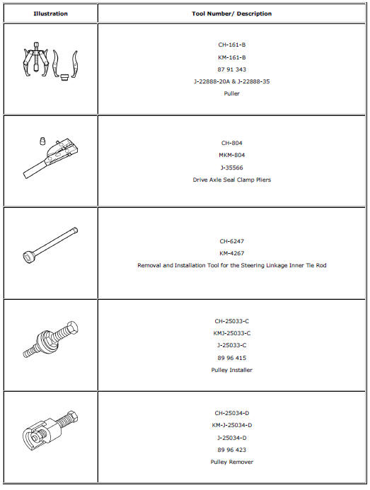
Special Tools and Equipment
 Power Steering System Description and Operation
The hydraulic power steering pump is a constant displacement vane-type pump
that provides hydraulic pressure and flow for the power
steering gear. The hydraulic power steering pumps are either belt ...
 Steering Wheel and Column
Specifications
...
Other materials:
Front Fog Lamps
For vehicles with front fog lamps, the button is on the outboard side of the
instrument panel.
The ignition must be on to turn on the fog lamps.
(Front Fog Lamps): Press
to turn the fog lamps on or off. An indicator light on the instrument cluster comes
on when the fog lamps are on.
The ...
Battery Disconnect Warning
Warning: Unless directed otherwise, the ignition and start switch
must be in the OFF or LOCK position, and all electrical loads must be
OFF before servicing any electrical component. Disconnect the negative battery
cable to prevent an electrical spark should a tool or
equipment come in contact ...
Additional links
Instrument Cluster Replacement
Preliminary Procedure
Remove instrument panel lower cluster trim plate. Refer to Instrument
Panel Cluster Lower Trim Plate Replacement.
Remove instrument panel steering column upper trim cover. Refer to
Steering Column Upper Trim Cover Replacement.
...
