Chevrolet Cruze Repair Manual: Front Seat Cushion Cover and Pad Replacement
Removal Procedure
Warning: Refer to SIR Warning in the Preface section.
Warning: Replace the passenger presence system as a complete assembly to prevent possible injury to the occupant. The bladder, the pressure sensor, the seat cushion, and the control module are assembled and calibrated as a unit. Using only some of the components in the service kit will cause the passenger presence system to operate improperly.
- Remove driver or passenger seat. Refer to Driver or Passenger Seat Replacement.
- Remove front seat adjuster handle, if equipped.
- Remove front seat recliner handle. Refer to Driver or Passenger Seat Recliner Handle Replacement.
- Remove seat cushion inner trim panel. Refer to Front Seat Cushion Inner Trim Panel Replacement.
- Remove seat cushion outer trim panel. Refer to Front Seat Cushion Outer Trim Panel Replacement.
- Detach cushion cover from backrest below.
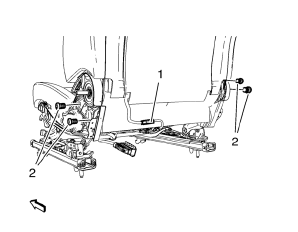
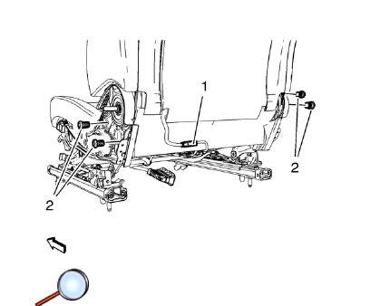
- Release and disconnect wiring harness plug (1), if equipped.
- Remove front seat backrest screw (2) (Qty: 4).
- Remove backrest.
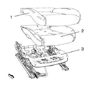
- Detach cushion cover (1) from seat frame (3) all the way round.
- Remove cushion cover (1) with pad (2) from frame (3).
- Remove cushion cover (1) from pad (2).
Installation Procedure

- Install cushion cover (1) to pad (2).
- Install cushion cover (1) with pad (2) to frame (3).
- Attach cushion cover (1) from seat frame (3) all the way round.
- Install backrest.
Caution: Refer to Fastener Caution in the Preface section.
- Tighten screw (2) (Qty: 4).
Tighten 35 N·m (26 lb ft)
- Connect and latch wiring harness plug (1), if equipped.
- Attach cushion cover to backrest below.
- Install seat cushion outer trim panel. Refer to Front Seat Cushion Outer Trim Panel Replacement.
- Install seat cushion inner trim panel. Refer to Front Seat Cushion Inner Trim Panel Replacement.
- Install front seat recliner handle. Refer to Driver or Passenger Seat Recliner Handle Replacement.
- Install front seat adjuster handle, if equipped.
- Install driver or passenger seat. Refer to Driver or Passenger Seat Replacement.
 Front Seat Track Synchronization
The fore/aft manual adjuster is composed of an inboard track assembly (5),
and outboard track (4) assembly, and an adjuster handle (1).
Each track assembly is made of an upper track (2) and a ...
 Driver or Passenger Seat Back Cushion Cover and Pad Replacement
Removal Procedure
Warning: Refer to SIR Warning in the Preface section.
Warning: Replace the passenger presence system as a complete assembly to prevent
possible injury to the occupant. The blad ...
Other materials:
Front End Inflatable Restraint Discriminating Sensor Replacement
Warning: Refer to SIR Warning in the Preface section.
Warning: Following the deployment of a side impact air bag, inspect the
following parts for damage. Replace these parts if
necessary:
The seat cushion frame
The seat recliner, if equipped
The seat adjuster
The seat back frame
...
Rear Bumper Fascia Outer Guide Replacement
Preliminary Procedure
Remove the rear bumper fascia. Refer to Rear Bumper Fascia Replacement.
Rear Bumper Fascia Outer Guide Rivet (Qty: 3)
Special Tools
BO-594-A Hand Rivet Tongs
For equivalent regional tools, refer to Special Tools.
Rear Bumper Fascia Outer Guide
...
Automatic Transmission Shift Lock Control Function Check
WARNING
When you are doing this inspection, the vehicle could move suddenly. If the
vehicle moves, you or others could be injured.
1. Before starting this check, be sure there is enough room around the vehicle.
It should be parked on a level surface.
2. Firmly apply the parking brake.
Be rea ...
