Chevrolet Cruze Repair Manual: Front Side Door Wiring Harness Replacement

Preliminary Procedure
Remove the front side door inner panel trim. Refer to Front Side Door Trim Replacement.
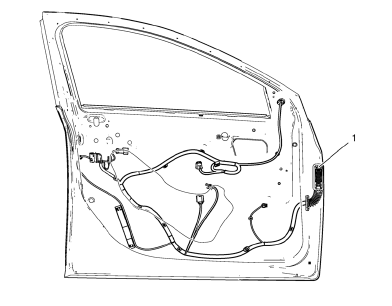
Front Side Door Wiring Harness
Warning: Unless directed otherwise, the ignition and start switch must be in the OFF or LOCK position, and all electrical loads must be OFF before servicing any electrical component. Disconnect the negative battery cable to prevent an electrical spark should a tool or equipment come in contact with an exposed electrical terminal. Failure to follow these precautions may result in personal injury and/or damage to the vehicle or its components.
For Vehicles equipped with OnStar® (UE1) with Back Up Battery: The Back Up Battery is a redundant power supply to allow limited OnStar® functionality in the event of a main vehicle battery power disruption to the VCIM (OnStar®module). Do not disconnect the main vehicle battery or remove the OnStar® fuse with the ignition key in any position other than OFF. Retained accessory power (RAP) should be allowed to time out or be disabled (simply opening the driver door should disable RAP) before disconnecting power. Disconnecting power to the OnStar® module in any way while the ignition is On or with RAP activated may cause activation of the OnStar® Back-Up Battery (BUB) system and will discharge and permanently damage the back-up battery. Once the Back-Up Battery is activated it will stay on until it has completely discharged. The BUB is not rechargeable and once activated the BUB must be replaced.
Procedure
- Disconnect the battery.
- Remove the water deflector.
- Disconnect electrical connectors as needed.
Rear Compartment Lid Wiring Harness Replacement

Preliminary Procedure
Remove the rear compartment lid inner panel trim. Refer to Rear Compartment Lid Inner Panel Trim Replacement.
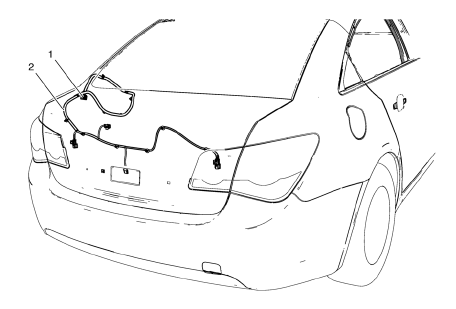
- Rear Compartment Lid Wiring Harness Plug
Procedure
- Disconnect the battery.
- Release the locking device to disconnect the wiring harness plug.
- Rear Compartment Lid Wiring Harness
 Front Fender Replacement
Preliminary Procedure
Remove the front bumper fascia. Refer to Front Bumper Fascia
Replacement
Remove front bumper fascia guide. Refer to Front Bumper Fascia
Replacement
Remove ...
 Rear Side Door Wiring Harness Replacement
Preliminary Procedure
Remove the rear side door inner panel trim. Refer to Rear Side Door Trim
Replacement.
Rear Side Door Wiring Harness
Warning: Unless directed otherwise, the ignition ...
Other materials:
Stabilizer Shaft Link Replacement
Preliminary Procedure
Raise and support the vehicle. Refer to Lifting and Jacking
the Vehicle.
Remove the front tire and wheel assemblies. Refer to Tire and Wheel
Removal and Installation.
Stabilizer Shaft Link Nut (Qty: 2)
Caution: Refer to Fastener Caution in the Pr ...
Brake Drum Replacement
Special Tools
CH 41013 Rotor Resurfacing Kit
CH 42450-A Wheel Hub Resurfacing Kit
For equivalent regional tools, refer to Special Tools.
Removal Procedure
Warning: Refer to Brake Dust Warning in the Preface section.
Check to ensure that the park brake is fully released
R ...
Removal Procedure
Warning: Refer to Approved Equipment for Collision Repair Warning in the
Preface section.
Warning: Refer to Glass and Sheet Metal Handling Warning in the Preface section.
Disable the SIR System. Refer to SIR Disabling
and Enabling.
Disconnect the negative battery cable. Refer to ...
