Chevrolet Cruze Repair Manual: Headlamp Replacement

Preliminary Procedure
Remove the front bumper fascia upper bracket. Refer to Front Bumper Fascia Replacement.
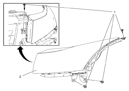
- Headlamp Screw (Qty: 4)
Caution: Refer to Fastener Caution in the Preface section.
Tip
Secure the headlamp fasteners in sequence, as indicated.
Tighten 2.5 N·m (22 lb in)
- Headlamp Assembly
Procedure
- Pull forward on the outside edge of the headlamp in order to release the up and down locator tabs on the backside of the headlamp.
- Pull forward on the top inside edge of the headlamp to release the inboard up/down locator.
- Pull the headlamp assembly down.
- Pull the headlamp assembly forward far enough to access the electrical connection.
- Disconnect the headlamp electrical connector from the forward lamp harness connector.
- Remove the headlamp assembly.
- Aim the headlamps after installation. Refer to Headlamp Aiming.
Headlamp Bulb Replacement

Preliminary Procedure
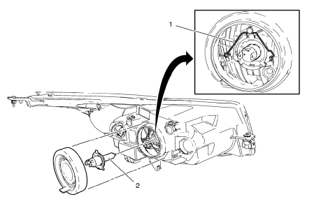
Remove the headlamp bulb dust cover.
- Headlamp Bulb Socket Bracket
Tip
Disconnect electrical connector.
- Headlamp Bulb
Warning: Refer to Halogen Bulb Warning in the Preface section.
Procedure
Remove the bulb from the lamp socket.
 Brake Pedal Position Sensor Calibration
Calibration Criteria
Note: Do not apply the brake pedal during the brake pedal position
(BPP) sensor calibration procedure. Any movement of the brake pedal
during this procedure will cause the cal ...
 Headlamp Aiming
...
Other materials:
Removal Procedure
Warning: Refer to Approved Equipment for Collision Repair Warning in the
Preface section.
Warning: Refer to Collision Sectioning Warning in the Preface section.
Warning: Refer to Glass and Sheet Metal Handling Warning in the Preface section.
Disable the SIR System. Refer to SIR Disabling ...
Front Fog Lamp Bulb Replacement
Preliminary Procedures
Raise and support the vehicle. Refer to Lifting and Jacking the Vehicle
Disconnect the forward lamp electrical harness connector from the fog
lamp bulb socket.
Remove the Front Bumper Fascia Opening Lower Cover. Refer to Front
Bumper Fascia Opening Lowe ...
Front Side Door Window Weatherstrip Replacement
Preliminary Procedure
Remove the outside rearview mirror. Refer to Outside Rearview
Mirror Replacement.
Remove the front side door window frame rear cover. Refer to Front Side
Door Window Frame Rear Cover Replacement.
Front Side Door Window Weatherstrip
Procedure
Pull the ...
