Chevrolet Cruze Repair Manual: Installation Procedure
- Install the following components on the drivetrain and front suspension frame:
- CH 49460-1 adapter (2).
- CH 49460-2 adapter (4).
- CH 6615-10 hydraulic cylinder (1).
- NEW frame insulator (3)
Note: Check marking of frame insulator.
- Press carefully the frame insulator in to the front suspension frame, using CH 6616 hand pump .
- Remove the following components from the drivetrain and front suspension frame:
- CH 49460-1 adapter .
- CH 49460-2 adapter .
- CH 6615-10 hydraulic cylinder .
- Install the drivetrain and front suspension frame. Refer to Drivetrain and Front Suspension Frame Replacement.
Front Wheelhouse Liner Replacement
Preliminary Procedure
Remove the tire and wheel assembly. Refer to Tire and Wheel Removal and Installation.
- Front Wheelhouse Liner Screw (Qty: 5)
Caution: Refer to Fastener Caution in the Preface section.
Tighten 2.5 N·m (23 lb in)
- Front Wheelhouse Liner Plastic Retainer (Qty: 7)
- Front Wheelhouse Liner
Rear Wheelhouse Panel Liner Replacement
Preliminary Procedure
Remove the tire and wheel assembly. Refer to Tire and Wheel Removal and Installation.
- Rear Wheelhouse Panel Liner Screw (Qty: 4)
Caution: Refer to Fastener Caution in the Preface section.
Tighten 2.5 N·m (23 lb in)
- Rear Wheelhouse Panel Liner Nut (Qty: 2)
Tighten 2.5 N·m (23 lb in)
- Rear Wheelhouse Panel Liner Plastic Retainer (Qty: 2)
- Rear Wheelhouse Panel Liner
Front Fog Lamp Bezel Replacement
Preliminary Procedure
- Remove front bumper fascia. Refer to Front Bumper Fascia Replacement.
- Remove front fog lamp. Refer to Front Fog Lamp Replacement.
Front Fog Lamp Bezel Screw
Caution: Refer to Fastener Caution in the Preface section.
Tighten 2.5 N·m (23 lb in)
Front Fog Lamp Bezel
Procedure
- Disengage the 4 inner retainer tabs securing the bezel to the front bumper fascia.
- Pull outward from the outer edge in order to release the outer retention clips securing the bezel to the front bumper fascia.
- Remove the front fog lamp bezel.
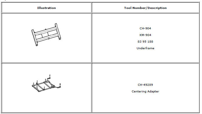
Special Tools and Equipment
 Removal Procedure
Remove the drivetrain and front suspension frame. Refer to Drivetrain
and Front Suspension Frame Replacement.
Mark Installation position of insulator (2) at frame (1).
...

Other materials:
Power Steering Pump Belt Replacement
Special Tools
CH 49800 Installer Power Steering Pump Belt
For equivalent regional tools, refer to Special Tools.
Removal Procedure
Caution: Do not use belt dressing on the drive belt. Belt dressing
causes the breakdown of the composition of the drive belt. Failure
to follow this recommendatio ...
Parking Brake
To apply the parking brake, pull up on the parking brake handle. It is not necessary
to push in on the release button while applying the parking brake. If the ignition
is in the ON/RUN position, the brake system warning light will come on.
To release the parking brake:
1. Hold the brake peda ...
Removal Procedure
Warning: Refer to Approved Equipment for Collision Repair Warning in the
Preface section.
Warning: Refer to Collision Sectioning Warning in the Preface section.
Warning: Refer to Glass and Sheet Metal Handling Warning in the Preface section.
Disable the SIR System. Refer to SIR Dis ...
