Chevrolet Cruze Repair Manual: Front End Upper Tie Bar Support Sectioning (MAG Welding)
Note: According to different corrosion warranties, only the regional mandatory joining methods are allowed.
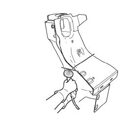
Removal Procedure
Warning: Refer to Approved Equipment for Collision Repair Warning in the Preface section.
Warning: Refer to Collision Sectioning Warning in the Preface section.
Warning: Refer to Glass and Sheet Metal Handling Warning in the Preface section.
- Disable the SIR System. Refer to SIR Disabling and Enabling.
- Disconnect the negative battery cable. Refer to Battery Negative Cable Disconnection and Connection.
- Remove all related panels and components.
- Visually inspect the damage. Repair as much of the damage as possible.
- Remove the sealers and anti-corrosion materials from the repair area, as necessary. Refer to Anti-Corrosion Treatment and Repair.
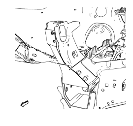
- Create cut lines on the front end upper tie bar.
- Cut the panel where sectioning is to be performed.
Note: Do not damage any inner panels or reinforcements.
- Locate and mark all the necessary factory welds of the front end upper tie bar.
- Drill all factory welds. Note the number and location of welds for installation of the service assembly.
- Remove the damaged f 10. ront end upper tie bar.
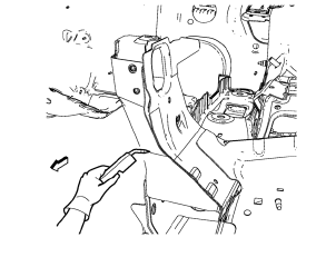
Installation Procedure
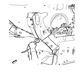
- Cut the front end upper tie bar in corresponding locations to fit the remaining original panel. The sectioning joint should be trimmed to allow a gap of one-and-one-half-times the metal thickness at the sectioning joint.
- Create a 50 mm (2 in) backing plate from the unused portion of the service part.
- Drill 8 mm (5/16 in) along the sectioning cut on the remaining original part. Locate these holes 13 mm (1/2 in) from the edge of part and spaced 40 mm (1 1/2 in) apart.
- Prepare all mating surfaces as necessary.
- Fit the backing plates halfway into the sectioning joints, clamp in place and plug weld to the vehicle.
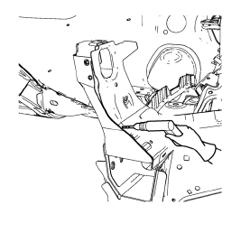
- Align the front end upper tie bar.
- Clean and prepare the attaching surfaces for welding.
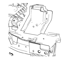
- Position the front end upper tie bar on the vehicle.
- Verify the fit of the front end upper tie bar.
- Clamp the front end upper tie bar into position.
- Plug weld accordingly.
- To create a solid weld with minimum heat distortion, make 25 mm (1 in) stitch welds along the seam with 25 mm (1 in) gaps between them. Then go back and complete the stitch weld.
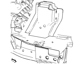
- Apply the sealers and anti-corrosion materials to the repair area, as necessary. Refer to Anti-Corrosion Treatment and Repair.
- Paint the repaired area. Refer to Basecoat/Clearcoat Paint Systems.
- Install all related panels and components.
- Connect the negative battery cable. Refer to Battery Negative Cable Disconnection and Connection.
- Enable the SIR system. Refer to SIR Disabling and Enabling.
 Headlamp Mount Panel Replacement (MIG-Brazing)
Note: According to different corrosion warranties, only the
regional mandatory joining methods are allowed.
Removal Procedure
Warning: Refer to Approved Equipment for Collision Repair Warning in t ...
 Front End Upper Tie Bar Support Sectioning (MIG Brazing)
Note: According to different corrosion warranties, only the
regional mandatory joining methods are allowed. ...
Other materials:
Loss of Control
Skidding
There are three types of skids that correspond to the vehicle's three control
systems:
• Braking Skid — wheels are not rolling.
• Steering or Cornering Skid — too much speed or steering in a curve causes tires
to slip and lose cornering force.
• Acceleration Skid — too much thro ...
Passenger Sensing System
United States
Canada
The passenger sensing system turns off the front outboard passenger frontal airbag
and knee airbag under certain conditions. No other airbag is affected by the passenger
sensing system.
The passenger airbag status indicator will be visible on the instrument panel
wh ...
Removal Procedure
Warning: Refer to Approved Equipment for Collision Repair Warning in
the Preface section.
Disable the SIR System. Refer to SIR Disabling
and Enabling.
Disconnect the negative battery cable. Refer to Battery Negative Cable
Disconnection and Connection.
Remove all related panels and co ...
