Chevrolet Cruze Repair Manual: Installation Procedure
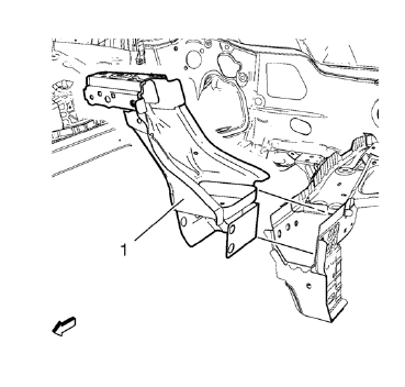
- Position the front end upper tie bar (1) on the vehicle.
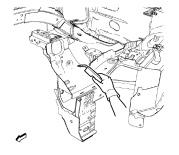
- Verify the fit of the front end upper tie bar.
- Clamp the front end upper tie bar into position.
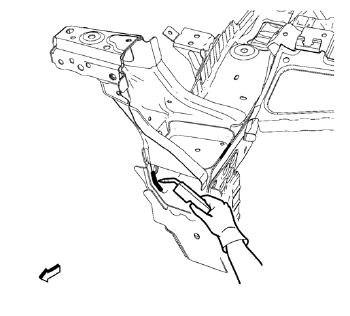
- Weld seam accordingly.
- Weld seam accordingly.
- Grind down weld seams as needed for related panels and components.
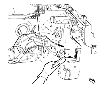
- Drill 8 mm (5/16 in) for plug welding along the edges of the service panel as noted from the original panel.
- Clean and prepare the attaching surfaces for welding.
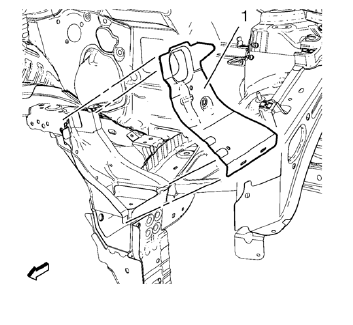
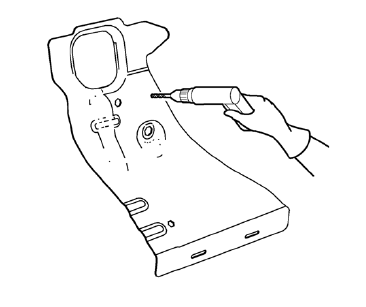
- Position the front end sheet metal cross panel reinforcement (1) on the vehicle.
- Verify the fit of the front end upper tie bar.
- Clamp the front end sheet metal cross panel reinforcement into position.
- Plug weld accordingly.
- Install front bumper impact bar before applying the sealers and anti-corrosion materials.
- Apply the sealers and anti-corrosion materials to the repair area, as necessary. Refer to Anti-Corrosion Treatment and Repair
- Paint the repaired area. Refer to Basecoat/Clearcoat Paint Systems
- Install all related panels and components
- Connect the negative battery cable. Refer to Battery Negative Cable Disconnection and Connection
- Enable the SIR system. Refer to SIR Disabling and Enabling
 Removal Procedure
Disable the SIR System. Refer to SIR Disabling and Enabling.
Disconnect the negative battery cable. Refer to Battery Negative Cable
Disconnection and Connection.
Remove all related panels an ...
 Front End Upper Tie Bar Replacement (MIG-Brazing)
Note: According to different corrosion warranties, only the
regional mandatory joining methods are allowed. ...
Other materials:
Interior Lamps Dimming
This group includes lamps which may dim. This group may use a combination of
vacuum fluorescent illumination, LEDs and incandescent
lamps
HVAC control module, head assembly
Rear HVAC control module, head assembly
Radio
Rear seat audio
The instrument panel cluster
The PRNDL lamp, wit ...
Satellite Radio
SiriusXM® Satellite Radio
Vehicles with a valid SiriusXM satellite radio subscription can receive SiriusXM
programming.
SiriusXM satellite radio has a wide variety of programming and commercial-free
music, coast to coast, and in digital-quality sound.
See www.siriusxm.com or call 1-866-635- ...
Rear Compartment Lid Emblem/Nameplate Replacement (Cruze - Left Side)
Rear Compartment Lid Emblem Assembly
Caution: Refer to Exterior Trim Emblem Removal Caution in the Preface
section.
Procedure
The part and surface should be 21°C (70°F) prior to installation. The
vehicle should remain 21°C (70°F) for
one hour after assembly to allow adhesive to deve ...
