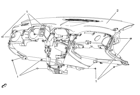
Chevrolet Cruze Repair Manual: Instrument Panel Assembly Replacement

Preliminary Procedures
- Disable the SIR system. Refer to SIR Disabling and Enabling
- Remove the front floor console assembly. Refer to Front Floor Console Replacement.
- Remove the radio assembly. Refer to Radio Replacement.
- Remove the driver information display bezel. Refer to Driver Information Display Bezel Replacement.
- Remove the heater and air conditioning control. Refer to Heater and Air Conditioning Control Replacement.
- Remove the steering column lower trim cover. Refer to Steering Column Lower Trim Cover Replacement
- Remove the steering column upper trim cover. Refer to Steering Column Upper Trim Cover Replacement.
- Remove both instrument panel outer trim covers. Refer to Instrument Panel Outer Trim Cover Replacement - Left Side.
- Remove the instrument panel compartment assembly. Refer to Instrument Panel Compartment Replacement.
- Remove the instrument panel molding. Refer to Instrument Panel Molding Replacement.
- Remove the center air outlet assembly. Refer to Instrument Panel Center Air Outlet Replacement.
- Remove the left outer air outlet assembly. Refer to Instrument Panel Outer Air Outlet Replacement - Left Side.
- Remove the right outer air outlet assembly. Refer to Instrument Panel Outer Air Outlet Replacement - Right Side.
- Instrument Panel Assembly Screw (Qty: 9)
Caution: Refer to Fastener Caution in the Preface section.
Tighten 9 N·m(80 lb in)
- Instrument Panel Assembly
Procedure
- Note location and routing of the instrument panel wiring harness prior to removal of the instrument panel assembly to ensure proper reinstallation.
- Disconnect the wiring harness from the instrument panel assembly.
- With the aid of an assistant, remove the instrument panel assembly from the vehicle.
- When replacing the instrument panel assembly, transfer all necessary components.
 Instrument Panel Upper Trim Pad Insert Replacement
Preliminary Procedure
Remove the instrument panel. Refer to Instrument Panel Assembly Replacement.
Instrument Panel Upper Trim Pad Insert Screw (Qty: 6)
Caution: Refer to Fastener Caution ...
 Instrument Panel Tie Bar Replacement (Right Hand Drive)
Removal Procedure
Remove instrument panel compartment. Refer to Instrument Panel
Compartment Replacement.
Remove instrument panel wiring harness (2) from instrument panel tie ba ...
Other materials:
Windshield Wiper/Washer
The windshield wiper/washer lever is on the right side of the steering column.
With the ignition in ACC/ ACCESSORY or ON/RUN, move the windshield wiper lever to
select the wiper speed.
HI: Use for fast wipes.
LO: Use for slow wipes.
INT: Move the lever up to INT for intermittent wipes, th ...
Trailer Towing (Except Fuel Economy Model)
Before pulling a trailer, there are three important considerations that have
to do with weight:
• The weight of the trailer.
• The weight of the trailer tongue.
• The total weight on your vehicle's tires.
Weight of the Trailer
How heavy can a trailer safely be? It should never weigh more ...
Adding Equipment to the Airbag-Equipped Vehicle
Adding accessories that change the vehicle's frame, bumper system, height, front
end, or side sheet metal, may keep the airbag system from working properly. The
operation of the airbag system can also be affected by changing or moving any parts
of the front seats, safety belts, the airbag ...
