Chevrolet Cruze Repair Manual: Removal Procedure
Warning: Refer to Approved Equipment for Collision Repair Warning in the Preface section.
Warning: Refer to Glass and Sheet Metal Handling Warning in the Preface section.
- Disable the SIR System. Refer to SIR Disabling and Enabling.
- Disconnect the negative battery cable. Refer to Battery Negative Cable Disconnection and Connection.
- Remove all related panels and components.
- Visually inspect the damage. Repair as much of the damage as possible.
- Remove the sealers and anti-corrosion materials from the repair area, as necessary. Refer to Anti-Corrosion Treatment and Repair.
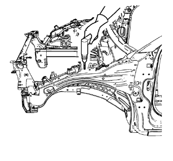
- Locate and mark all the necessary factory welds and weld seams of the front compartment upper side rail.
- Drill all factory welds. Note the number and location of welds for installation of the service assembly.
- Grind factory weld seams.
- Remove the front compartment upper side rail.
 Front Compartment Upper Side Rail Replacement (MAG-Welding)
Note: According to different corrosion warranties, only the
regional mandatory joining methods are allowed. ...
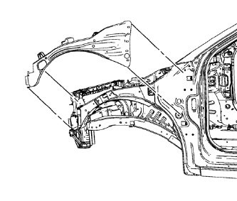
 Installation Procedure
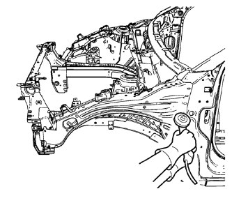
Drill 8 mm (5/16 in) for plug welding along the edges of the front
compartment upper side rail as noted from the original panel.
Clean and prepare the attaching surfaces for welding. ...
Other materials:
Stitcher Internet Radio
Stitcher SmartRadio™ is an Internet radio service that streams news, sports,
and entertainment shows through the audio system. Create personalized, on-demand
stations or discover new shows through Stitcher's preset stations. To set up an
account, download the application from the Android M ...
Front Wheel Drive Shaft Replacement - Right Side
Special Tools
CH-313 Slide Hammer
CH-6003 Axle Shaft Remover
CH-49376 Holding Wrench
CH-49400 Hub Spindle Remover
DT-6332 Seal Protector
EN-956-1 Extension
For equivalent regional tools, refer to Special Tools.
Removal Procedure
Warning: To prevent personal injury and/or component ...
Rear Seat Back Cushion Cover and Pad Replacement - Left Side
Preliminary Procedure
Remove rear seat - left side. Refer to Rear Seat Replacement
Rear Seat Back Cushion Cover
Procedure
Remove the staples from the seat back cover.
Remove seat back cushion cover from Velcro.
Rear Seat Back Cushion Pad
Rear Seat Back Cushion Cover and Pad Re ...
