Chevrolet Cruze Repair Manual: Removal Procedure
Warning: Refer to Approved Equipment for Collision Repair Warning in the Preface section.
Warning: Refer to Collision Sectioning Warning in the Preface section.
Warning: Refer to Glass and Sheet Metal Handling Warning in the Preface section.
- Disable the SIR System. Refer to SIR Disabling and Enabling.
- Disconnect the negative battery cable. Refer to Battery Negative Cable Disconnection and Connection.
- Remove all related panels and components.
- Visually inspect the damage. Repair as much of the damage as possible.
- Remove the sealers and anti-corrosion materials from the repair area, as necessary. Refer to Anti-Corrosion Treatment and Repair.
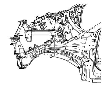
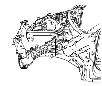
- Create cut lines on the front compartment upper side rail.
Note: Do not damage any inner panels or reinforcements.
- Cut the panel where sectioning is to be performed.
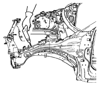
- Locate and mark all the necessary factory welds of the front compartment upper side rail.
- Drill all factory welds. Note the number and location of welds for installation of the service assembly.
- Remove the damaged front 10. compartment upper side rail.
 Front Compartment Upper Side Rail Sectioning (MIG-Brazing)
Note: According to different corrosion warranties, only the
regional mandatory joining methods are allowed. ...
 Installation Procedure
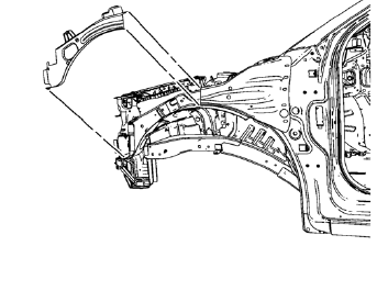
Cut the front compartment upper side rail in corresponding locations to
fit the remaining original panel. The sectioning joint should
be trimmed to allow a gap of one-and-one-half-times th ...
Other materials:
Vehicle Messages
Messages displayed on the DIC indicate the status of the vehicle or some action
that may be needed to correct a condition. Multiple messages may display one after
the other.
The messages that do not require immediate action can be acknowledged and cleared
by pressing SET/CLR. The messages tha ...
Tire Pressure Monitor Operation
This vehicle may have a Tire Pressure Monitor System (TPMS).
The TPMS is designed to warn the driver when a low tire pressure condition exists.
TPMS sensors are mounted onto each tire and wheel assembly, excluding the spare
tire and wheel assembly. The TPMS sensors monitor the air pressure in t ...
Replacing Safety Belt System Parts after a Crash
WARNING
A crash can damage the safety belt system in the vehicle.
A damaged safety belt system may not properly protect the person using it, resulting
in serious injury or even death in a crash. To help make sure the safety belt systems
are working properly after a crash, have them inspected a ...
