Chevrolet Cruze Repair Manual: Removal Procedure
Warning: Refer to Approved Equipment for Collision Repair Warning in the Preface section.
Warning: Refer to Collision Sectioning Warning in the Preface section.
Warning: Refer to Glass and Sheet Metal Handling Warning in the Preface section.
- Disable the SIR System. Refer to SIR Disabling and Enabling.
- Disconnect the negative battery cable. Refer to Battery Negative Cable Disconnection and Connection.
- Remove all related panels and components.
- Visually inspect the damage. Repair as much of the damage as possible.
- Remove the sealers and anti-corrosion materials from the repair area, as necessary. Refer to Anti-Corrosion Treatment and Repair.
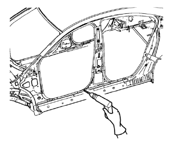
- Locate and mark all the necessary factory welds of the body side outer panel reinforcement.
- Drill all factory welds. Note the number and location of welds for installation of the service assembly.
- Remove the damaged body side outer panel reinforcement.
 Body Side Outer Panel Reinforcement Replacement (MIG-Brazing)
Note: According to different corrosion warranties, only the
regional mandatory joining methods are allowed. ...
 Installation Procedure
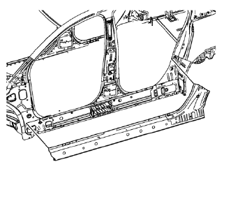
Align the body side outer panel reinforcement.
Clean and prepare the attaching surfaces for welding.
Position the body side outer panel
reinforcement on the vehicle.
Verify ...
Other materials:
Front Side Door Trim Replacement
Front Side Door Pull Handle Bolt
Caution: Refer to Fastener Caution in the Preface section.
Tighten
2 N·m (18 lb in)
Front Side Door Inside Handle Bolt Finish Cap
Tip
Pull handle back to remove cap. Use suitable tool to unsnap.
Front Side Door Inside Handle Bolt
Tighten
...
Strut Assembly Replacement
Special Tools
CH 49375 Wrench
For equivalent regional tools, refer to Special Tools.
Removal Procedure
Raise and the vehicle. Refer to Lifting and Jacking the Vehicle.
Remove the tire and wheel assembly. Refer to Tire and Wheel Removal and
Installation.
Separate the brake hose ...
Introduction
The names, logos, emblems, slogans, vehicle model names, and vehicle body designs
appearing in this manual including, but not limited to, GM, the GM logo, CHEVROLET,
the CHEVROLET Emblem, and CRUZE are trademarks and/or service marks of General Motors
LLC, its subsidiaries, affiliates, or li ...
