Chevrolet Cruze Repair Manual: Removal Procedure
Warning: Refer to Approved Equipment for Collision Repair Warning in the Preface section.
Warning: Refer to Glass and Sheet Metal Handling Warning in the Preface section.
- Disable the SIR System. Refer to SIR Disabling and Enabling.
- Disconnect the negative battery cable. Refer to Battery Negative Cable Disconnection and Connection.
- Remove all related panels and components.
- Visually inspect the damage. Repair as much of the damage as possible.
- Remove the sealers and anti-corrosion materials from the repair area, as necessary. Refer to Anti-Corrosion Treatment and Repair.
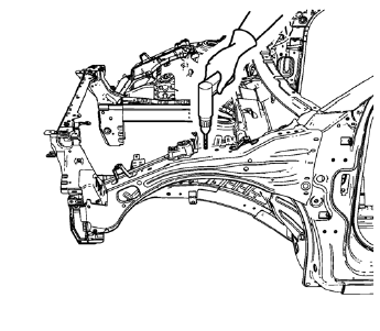
- Locate and mark all the necessary factory welds and weld seams of the front compartment upper side rail.
- Drill all factory welds. Note the number and location of welds for installation of the service assembly.
- Grind factory weld seams.
- Remove the front compartment upper side rail.
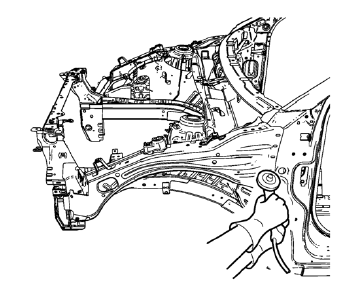
 Front Compartment Upper Side Rail Replacement (MIG-Brazing)
Note: According to different corrosion warranties, only the
regional mandatory joining methods are allowed. ...
 Installation Procedure
Create 5 x 18 mm (4/16 x 11/16 in) slots for MIG-brazing
(1).
Clean and prepare the attaching surfaces for spot welding and brazing.
Note: In MIG-brazing areas 50 mm (2 in) ...
Other materials:
Luggage Compartment Description and Operation
Rear Compartment Lid Release System Components
Body control module (BCM)
Exterior rear compartment lid release switch
Rear compartment lid release actuator
Rear compartment lid release relay
Rear Compartment Lid Release Operation
When the exterior rear compartment lid release switch is ...
Shifting out of Park
This vehicle is equipped with an automatic transmission shift lock control system.
The shift lock is designed to:
• Prevent ignition key removal unless the shift lever is in P (Park) with the shift
lever button fully released.
• Prevent movement of the shift lever out of P (Park) unless the ig ...
Instrument Panel Compartment Replacement
Preliminary Procedure
Remove the instrument panel outer trim cover - right side. Refer to
Instrument Panel Outer Trim Cover Replacement - Right Side.
Instrument Panel Compartment Screw (Qty: 5)
Caution: Refer to Fastener Caution in the Preface section.
Tighten
2.5 N·m (22 lb in)
...
