Chevrolet Cruze Repair Manual: Removal Procedure
Warning: Refer to Approved Equipment for Collision Repair Warning in the Preface section.
Warning: Refer to Glass and Sheet Metal Handling Warning in the Preface section.
- Disable the SIR System. Refer to SIR Disabling and Enabling.
- Disconnect the negative battery cable. Refer to Battery Negative Cable Disconnection and Connection.
- Remove all related panels and components.
- Visually inspect the damage. Repair as much of the damage as possible.
- Remove the sealers and anti-corrosion materials from the repair area, as necessary. Refer to Anti-Corrosion Treatment and Repair.
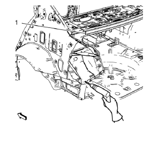
- Locate and mark all the necessary factory welds of the body rear end panel.
Note: Drill factory welds in area of the rear end upper panel reinforcement (1) from above. Create slots out of the drill holes for later brazing.
- Drill all factory welds. Note the number and location of welds for installation of the service assembly.
- Remove the tail lamp pocket.
 Tail Lamp Pocket Replacement (MIG-Brazing)
Note: According to different corrosion warranties, only the
regional mandatory joining methods are allowed. ...
 Installation Procedure
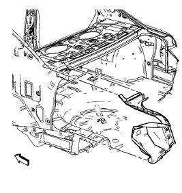
Create 5 x 18 mm (4/16 x 11/16 in) slots for MIG-brazing along the edges
of the tail lamp pocket as noted f rom the
original panel.
Note:
Clean and prepare the attaching surf ...
Other materials:
Overview
1.
• Turns the system on or off and adjusts the volume.
2. Buttons 1 to 6
• Radio: Saves and selects favorite stations.
3.
• Radio: Seeks the previous station.
• CD: Selects the previous track or rewinds within a track.
4.
• CD: Pauses playback, and stops playback.
5.
• Radio: ...
Rear Side Door Adjustment
Rear Side Door
Caution: Refer to Fastener Caution in the Preface section.
Procedure
Loosen the rear door hinge bolt (Qty: 4) to adjust the rear door.
Adjust the rear door in order to obtain an even gap between the rear
door and the roof, the quarter outer panel, the
rocker pan ...
Installation Procedure
Cut the quarter outer panel in corresponding locations to fit the
remaining original panel. The sectioning joint should be trimmed to
allow a gap of one-and-one-half-times the metal thickness at the sectioning
joint.
Create a 50 mm (2 in) backing plate from the unused portion
&nbs ...
