Chevrolet Cruze Repair Manual: Steering Gear Replacement (Hydraulic Power Steering)
Special Tools
EN 45059 Torque Angle Sensor Kit
For equivalent regional tools, refer to Special Tools.
Removal Procedure
- Turn the front wheels to the straight forward position and secure the steering wheel from moving.
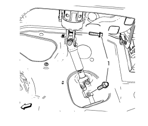
- Remove the lower steering intermediate shaft bolt (1).
- Remove the steering intermediate shaft from the steering gear.
- Raise and support the vehicle. Refer to Lifting and Jacking the Vehicle.
- Remove the tire and wheel assemblies. Refer to Tire and Wheel Removal and Installation.
- Remove the exhaust flexible pipe. Refer to Exhaust Flexible Pipe Replacement.
- Remove the front compartment splash shield. Refer to Front Compartment Splash Shield Replacement.
- Remove the front compartment insulator, if equipped. Refer to Front Compartment Insulator Replacement.
- Remove the steering linkage inner tie rod. Refer to Steering Linkage Inner Tie Rod Replacement.
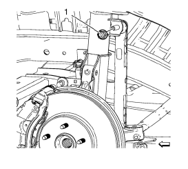
- Remove and discard the stabilizer link shaft nut (1) from the strut.
- Remove the stabilizer link shaft from the strut.
- Place a large container under the vehicle in order to collect the draining fluid.
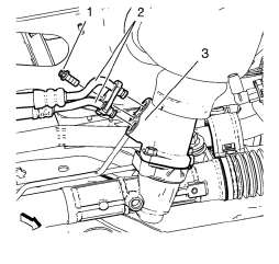
- Remove the power steering gear inlet and outlet hose bolt (1), remove the inlet and outlet hose (2) from the steering gear (3).
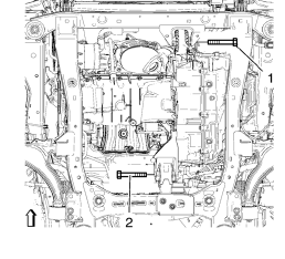
- Remove the front (1) and the rear (2) transmission mount bracket bolts.
- Remove the rear frame to body bolts. Refer to drivetrain and front suspension frame replacement Drivetrain and Front Suspension Frame Replacement
- Lower the rear of the frame max. 50 mm (1.968 in) in order to gain clearance to the steering gear.
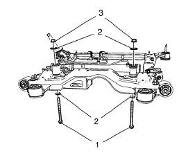
- Remove and discard the steering gear bolts (1), nuts (3) and washers (2) from the steering gear.
- Remove the steering gear.
Installation Procedure
- Install the steering gear.
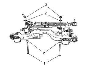
- Install steering gear bolts (1), washers (2) and nuts (3) to the steering gear.
Caution: Refer to Fastener Caution in the Preface section.
- Tighten the NEW steering gear bolts to 125 N·m (93 lb ft) + 160° , using the EN 45059 kit .
- Raise the frame with hydraulic jack.
- Install the rear frame to body bolts. Refer to drivetrain and front suspension frame replacement Drivetrain and Front Suspension Frame Replacement.
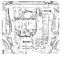
- Install the front transmission mount bolt (1) and tighten to 58 N·m (43 lb ft).
- Install the rear transmission mount bracket bolt (2) and tighten to 100 N·m (74 lb ft).
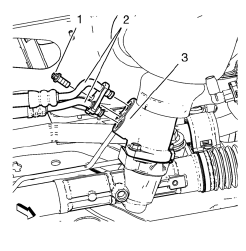
- Replace the O-rings of the inlet and outlet hoses. Lubricate O-rings with a small amount of hydraulic oil.
- Install the inlet and outlet hose (2) to the steering gear (3) and install the power steering gear inlet and outlet hose bolt (1). Tighten the power steering inlet and outlet hose bolt to 11 N·m (98 lb in).
- Install the stabilizer shaft link to the strut.
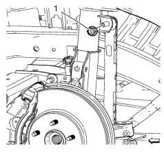
- Install the NEW stabilizer shaft link nut (1) and tighten to 65 N·m (48 lb ft).
- Install the steering linkage inner tie rod. Refer to Steering Linkage Inner Tie Rod Replacement.
- Install the front compartment insulator, if equipped. Refer to Front Compartment Insulator Replacement.
- Install the front compartment splash shield. Refer to Front Compartment Splash Shield Replacement.
- Install the exhaust flexible pipe. Refer to Exhaust Flexible Pipe Replacement.
- Install the front tire and wheel assemblies. Refer to Tire and Wheel Removal and Installation.
- Lower the vehicle.
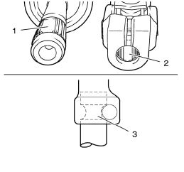
Note: The recess (2) of the fine toothing in the universal joint have to align precisely with the recess (1) of the fine toothing on the steering pinion. The bore in the universal joint have to align with the groove on the steering pinion (3).
- Check alignment of fine toothing of universal joint and steering pinion.
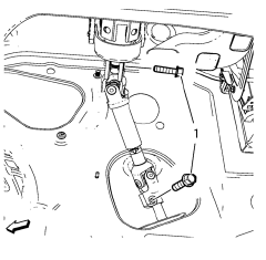
- Install the lower intermediate steering shaft bolts and tighten to 34 N·m (26 lb ft).
- Adjust the front toe. Refer to Wheel Alignment - Steering Wheel Angle and/or Front Toe Adjustment.
- Bleed the hydraulic steering system. Refer to Power Steering System Bleeding.
 Power Steering Gear Inlet Pipe/Hose Replacement
Removal Procedure
Remove front bumper fascia. Refer to Front Bumper Fascia Replacement
Remove as much power steering fluid from the remote power steering fluid
reservoir as possible.
Place ...
 Steering Linkage Inner Tie Rod Replacement (Hydraulic Power Steering)
Special Tools
CH-6247 Removal and Installation Tool for the Steering Linkage Inner Tie Rod
For equivalent regional tools, refer to Special Tools.
Removal Procedure
Raise and support the vehicle ...
Other materials:
General Information
Your vehicle is an important investment. This section describes the required
maintenance for the vehicle. Follow this schedule to help protect against major
repair expenses resulting from neglect or inadequate maintenance. It may also help
to maintain the value of the vehicle if it is sold. It ...
Front Side Door Replacement
Preliminary Procedure
Remove the front side door trim panel. Refer to Front Side Door Trim
Replacement.
Front Side Door Check Link Bolt
Caution: Refer to Fastener Caution in the Preface section.
Procedure
Remove the water deflector.
Disconnect the door electrical connector.
Su ...
Work Stall Test Warning
Warning: One or more of the following guidelines may apply when performing
specific required tests in the work stall:
When a test requires spinning the drive wheels with the vehicle jacked up,
adhere to the following precautions:
Do not exceed 56 km/h (35 mph) when spinning one drive wheel ...
