Chevrolet Cruze Repair Manual: Headlamp Mount Panel Replacement (MIG-Brazing)
Note: According to different corrosion warranties, only the regional mandatory joining methods are allowed.
Removal Procedure
Warning: Refer to Approved Equipment for Collision Repair Warning in the Preface section.
Warning: Refer to Glass and Sheet Metal Handling Warning in the Preface section.
- Disable the SIR System. Refer to SIR Disabling and Enabling.
- Disconnect the negative battery cable. Refer to Battery Negative Cable Disconnection and Connection.
- Remove all related panels and components.
- Visually inspect the damage. Repair as much of the damage as possible.
- Remove the sealers and anti-corrosion materials from the repair area, as necessary. Refer to Anti-Corrosion Treatment and Repair.
- Locate and mark all the necessary factory welds of the headlamp mount panel.
- Drill all factory welds. Note the number and location of welds for installation of the service assembly.
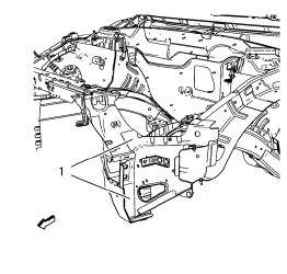
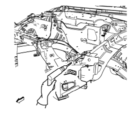
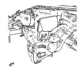
- Cut the adhesive (1) with an appropriate tool.
- Remove the headlamp mount panel.
Installation Procedure
- Clean and prepare the attaching surfaces for welding.
- Apply structural adhesive in areas noted from the original panel.
- Position the headlamp mount panel on the vehicle.
- Verify the fit of the headlamp mount panel.
- Clamp the headlamp mount panel into position.
- Spot weld accordingly.
- Apply the sealers and anti-corrosion materials to the repair area, as necessary. Refer to Anti-Corrosion Treatment and Repair.
- Paint the repaired area. Refer to Basecoat/Clearcoat Paint Systems.
- Install all related panels and components.
- Connect the negative battery cable. Refer to Battery Negative Cable Disconnection and Connection.
- Enable the SIR system. Refer to SIR Disabling and Enabling.
 Headlamp Mount Panel Replacement (MAG-Welding)
Note: According to different corrosion warranties, only the
regional mandatory joining methods are allowed.
Removal Procedure
Warning: Refer to Approved Equipment for Collision Repair Warning in t ...
 Front End Upper Tie Bar Support Sectioning (MAG Welding)
Note: According to different corrosion warranties, only the
regional mandatory joining methods are allowed.
Removal Procedure
Warning: Refer to Approved Equipment for Collision Repair Warning in t ...
Other materials:
Destination
If route guidance is not active, press the Destination Entry screen button on
the Home Page to access the Destination Entry screen. Several options can be selected
to plan a route by entering destinations.
Some destination entry items such as Previous Destinations, Address Book, and
My Home ...
Fuel
Use of the recommended fuel is an important part of the proper maintenance of
this vehicle. To help keep the engine clean and maintain optimum vehicle performance,
we recommend the use of gasoline advertised as TOP TIER Detergent Gasoline.
Look for the TOP TIER label on the fuel pump to ensure ...
Front Side Door Check Replacement
Prliminary Procedure
Remove front side door trim panel. Refer to Front Side Door Trim
Replacement
Remove the front side door water deflector. Refer to Front Side Door
Water Deflector Replacement
Front Side Door Check Link Bolt
Caution: Refer to Fastener Caution in the ...
