Chevrolet Cruze Repair Manual: Installation Procedure
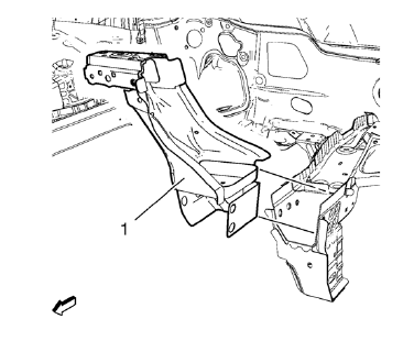
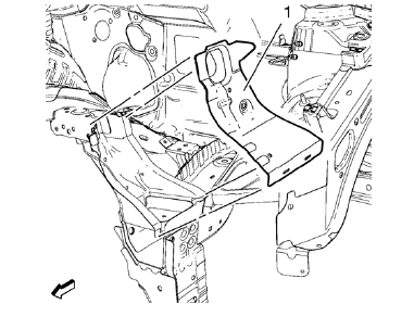
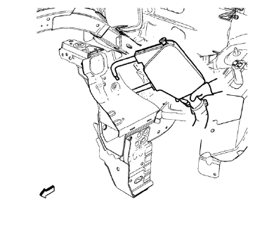
- Position the front end upper tie bar (1) on the vehicle.
- Verify the fit of the front end upper tie bar.
- Clamp the front end upper tie bar into position.
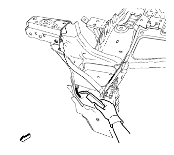
- Braze accordingly.
- Braze accordingly.
- Grind down weld seams as needed for related panels and components.
- Clean and prepare the attaching surfaces for welding.
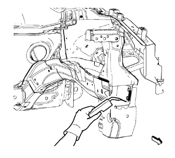
- Position the front end sheet metal cross panel reinforcement (1) on the vehicle.
- Verify the fit of the front end upper tie bar.
- Clamp the front end sheet metal cross panel reinforcement into position.
- Spot weld accordingly.
- Use factory slots for slot brazing.
- Install front bumper impact bar before applying the sealers and anti-corrosion materials.
- Apply the sealers and anti-corrosion materials to the repair area, as necessary. Refer to Anti-Corrosion Treatment and Repair
- Paint the repaired area. Refer to Basecoat/Clearcoat Paint Systems
- Install all related panels and components.
- Connect the negative battery cable. Refer to Battery Negative Cable Disconnection and Connection
- Enable the SIR system. Refer to SIR Disabling and Enabling
 Removal Procedure
Warning: Refer to Approved Equipment for Collision Repair Warning in the
Preface section.
Warning: Refer to Glass and Sheet Metal Handling Warning in the Preface section.
Disable the SIR System. ...
 Drivetrain and Front Suspension Frame Front Support Replacement (MAG-Welding)
Note: According to different corrosion warranties, only the
regional mandatory joining methods are allowed. ...
Other materials:
Courtesy/Illuminated Entry Lamps
The following lamps may be manually turned ON by placing the interior lamp
switch in the ON position, or by opening a door while the
switch is in the AUTO position.
The dome lamp
The liftgate lamps
Courtesy lamps
The courtesy lamp supply voltage circuit of the body control module (BCM) ...
Heated Oxygen and Oxygen Sensor Caution
Caution: Do not remove the pigtail from either the heated oxygen
sensor (HO2S) or the oxygen sensor (O2S). Removing the pigtail or the
connector will affect sensor operation.
Handle the oxygen sensor carefully. Do not drop the HO2S. Keep the in-line
electrical connector and the louvered end fr ...
Repairs and Inspections Required After a Collision
Warning: Restraint systems can be damaged in a collision. To help
avoid injury and ensure that all parts in need of replacement are
replaced:
Replace any seat belt system that was in use during the
collision serious enough to deploy any automatic restraint device such as
air
bags and ...
