Chevrolet Cruze Repair Manual: Removal Procedure
- Turn the front wheels to the straight forward position and secure the steering wheel from moving.
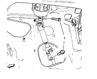
- Remove the 2 lower steering intermediate shaft bolts (1).
- Remove the steering intermediate shaft from the steering gear.
- Raise and support the vehicle. Refer to Lifting and Jacking the Vehicle
- Remove the tire and wheel assemblies. Refer to Tire and Wheel Removal and Installation
- Remove the front compartment insulator, if equipped.
- Remove the engine shield, if equipped
- Remove the exhaust flexible pipe. Refer to Exhaust Flexible Pipe Replacement.
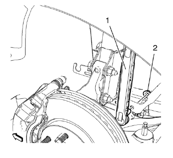
- Remove lower stabilizer link shaft nut (2) on both sides.
- Remove stabilizer link shaft (1) from stabilizer shaft.
- Remove stabilizer link shaft (1) from stabilizer.
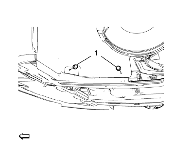
- Remove 4 fasteners (1) for the engine side cover on both sides.
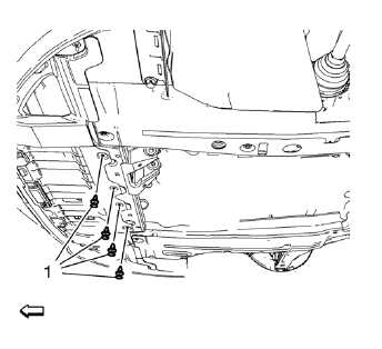
- Remove 4 fasteners (1) for the front engine compartment cover.
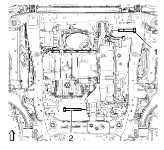
- Remove the front and rear transmission mount bracket bolts (1, 2).
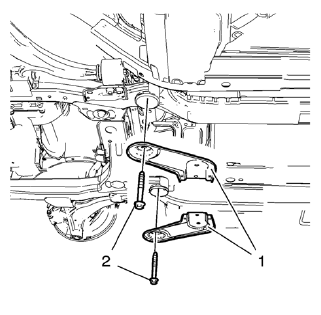
- Remove and DISCARD 2 rear suspension frame bolts (2).
Remove rear frame reinforcements (1).

- Position and set hydraulic lifter in connection with CH 904 frame and CH 49289-50 adapter (2) onto suspension frame (1). Bent from cover beside.
- Lower suspension frame max. 55 mm.
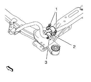
Note: In order to assure a correct installation of the insulators ONLY remove and install the insulators side by side! Dismantled MUST BE discarded.
- Remove and discard the two front stabilizer shaft insulator clamp bolts (1).
- Remove the shaft insulator clamp (2).
Bend up clamp (2) slightly.
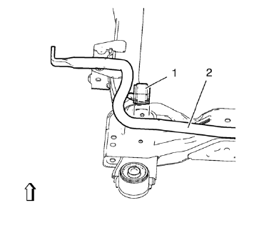
- Mark the location of the insulator (1) to the stabilizer shaft (2).
- Remove insulator (1) from stabilizer shaft (2).
 Stabilizer Shaft Insulator Replacement
Special Tools
CH 904 Underframe
EN 45059 Torque Angle Sensor Kit
CH 49289 Centering Adapter
For equivalent regional tools, refer to Special Tools. ...
 Installation Procedure
Install NEW stabilizer shaft insulators (1) to stabilizer shaft (2) so
that the slit in the insulator is facing the rear of the vehicle.
Install the insulator c 2. lamp to the insu ...
Other materials:
Ultra High Strength Dual Phase Steel
This information provides repair recommendations and general guidelines for
steel classified as Ultra High Strength Dual Phase Steel (Dual
Phase Steel with a tensile strength greater than 800 MPa), also known as DPX.
General Motors recommends the following when repairing or replacing this type ...
Removal Procedure
Disable the SIR System. Refer to SIR Disabling and Enabling.
Disconnect the negative battery cable. Refer to Battery Negative Cable
Disconnection and Connection.
Remove all related panels and components.
Visually inspect the damage. Repair as much of the damage as possible.
Remove the ...
Cruise Control
For vehicles with cruise control:
: Press to turn the cruise control system on and off.
RES/+: Move the thumbwheel up to resume a previously set speed or to accelerate.
SET/−: Move the thumbwheel down to set a speed or to make the vehicle decelerate.
: Press to disengage cruise contro ...
