
Chevrolet Cruze Repair Manual: SIR System Description and Operation
SIR System Overview
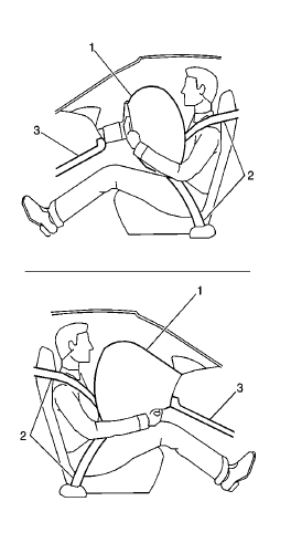
The supplemental inflatable restraint (SIR) system supplements the protection offered by the occupants Seat Belt System (2). The SIR system may contain several inflator modules located throughout the vehicle, i.e. steering wheel module (1), instrument panel module (1), or roof rail modules (1). In addition to inflator modules, the vehicle may contain seat belt pretensioners (2) that tighten the seat belt in the event of a collision, thus reducing the distance between the occupant and the seat belt when an inflator module is deployed. Each inflator module has a deployment loop that is controlled by the inflatable restraint sensing and diagnostic module (SDM) mounted inside the vehicle. The SDM determines the severity of a collision with the assistance of various sensor inputs located at strategic points on the vehicle. When the SDM detects a collision, it will process the information provided by the sensors to further support air bag or pretensioner deployment. The SDM will deploy the frontal air bags and pretensioners if it detects a collision of sufficient force. If the force of the impact is not sufficient to warrant inflator module deployment, the SDM may still deploy the seat belt pretensioners. The SDM performs continuous diagnostic monitoring of the SIR system electrical components. Upon detection of a circuit malfunction, the SDM will set a DTC and inform the driver by illuminating the AIR BAG indicator. The steering column (3) and knee bolsters (3) are designed to absorb energy and compress during frontal collisions in order to limit leg movement and decrease the chance of injury to the driver and passenger.
- Frontal SIR System Description
- Inflatable Restraint Passenger Presence Detection System - If Equipped
- Dual Stage Inflator Modules
- Inflatable Restraint Seat Position Sensors - If Equipped
- Inflatable Restraint Roof Rail Modules
 Deployment Outside Vehicle for Seat Belt Pretensioners
Deploy the seat belt pretensioners outside of the vehicle when the vehicle
will be returned to service. Situations that require deployment
outside of the vehicle include the following:
Using th ...
 Frontal SIR System Description
The frontal supplemental inflatable restraint (SIR) system consists of the
following components:
AIR BAG indicator located in the instrument cluster
Inflatable restraint sensing and diagnostic ...
Other materials:
Information Displays
Driver Information Center (DIC)
The DIC displays information about your vehicle. It also displays warning messages
if a system problem is detected.
DIC Operation and Displays
The DIC has different displays which can be accessed by using the DIC buttons
on the turn signal lever.
The DIC displ ...
Removal Procedure
Warning: Refer to Approved Equipment for Collision Repair Warning in the
Preface section.
Warning: Refer to Glass and Sheet Metal Handling Warning in the Preface section.
Disable the SIR System. Refer to SIR Disabling
and Enabling.
Disconnect the negative battery cable. Refer to ...
Rear Wheel Bearing and Hub Replacement (Drum Brake)
Special Tools
EN 45059 Torque Angle Sensor Kit
For equivalent regional tools, refer to Special Tools.
Removal Procedure
Raise and suitably support the vehicle. Refer to Lifting and
Jacking the Vehicle.
Remove the tire and wheel assembly. Refer to Tire and Wheel Removal and
...
