Chevrolet Cruze Repair Manual: Steering Wheel Inflatable Restraint Module Replacement
Removal Procedure
Warning: When carrying a live inflator module, make sure the bag opening is pointed away from you. This minimizes the chance of injury in the case of an accidental deployment. Never carry the inflator module by the wires. Never carry the inflator module by the connector on the underside of the module.
Make sure that the bag and trim cover are facing up whenever you place a live inflator module on any surface. This is necessary to provide a free space for the bag to expand in the unlikely event of accidental deployment. Never rest the steering column assembly on the steering wheel with the inflator module face down, and the column vertical. This may result in personal injury.
Warning: Refer to SIR Warning in the Preface section.
- Disable the supplemental inflatable restraint (SIR) system. Refer to SIR Disabling and Enabling.
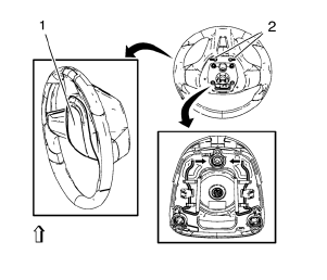
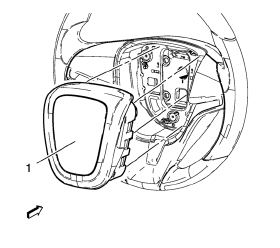
- Insert suitable tools to the openings (2) on both sides of the steering wheel (1).
- Release the springs in direction of the arrows.
- Disconnect the electrical connectors.
Installation Procedure
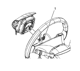
- Connect the electrical connectors (1).
- Align the steering wheel module fasteners to the steering column fastener holes.
- Push the steering wheel module (1) firmly into the steering column in order the engage the fasteners.
- Enable the SIR system. Refer to SIR 4. Disabling and Enabling.
- After replacing the module, fully deploy the old module before disposal.
 Inflatable Restraint Side Impact Sensor Replacement
Warning: Refer to SIR Warning in the Preface section.
Warning: Refer to SIR Inflator Module Handling and Storage Warning in the
Preface section.
Warning: Following the deployment of a side ...
 Steering Wheel Inflatable Restraint Module Coil Replacement
Preliminary Procedure
Remove the steering column upper trim cover. Refer to Steering Column
Upper Trim Cover Replacement.
Remove the steering column lower trim cover. Refer to Steer ...
Other materials:
When It Is Time for New Tires
Factors such as maintenance, temperatures, driving speeds, vehicle loading, and
road conditions affect the wear rate of the tires.
Treadwear indicators are one way to tell when it is time for new tires.
Treadwear indicators appear when the tires have only 1.6mm (1/16 in) or less
of tread rem ...
Aluminum Wheel Refinishing
Finish Damage Evaluation Procedure
Note:
If the wheels are chrome-plated, do not re-plate or refinish the
wheels.
If the wheels are polished aluminum, do not refinish the wheels in
the dealer environment. Utilize a refinisher that meets
manufacturer guidelines.
Inspect the wheel ...
Door Ajar Indicator Description and Operation
Door Ajar Indicator System Components
The door ajar indicator system consists of the following components:
Body control module (BCM)
Instrument cluster
Driver information center
Driver door latch
Passenger door latch
Left rear door latch
Right rear door latch
Liftgate door latch
...
