Chevrolet Cruze Repair Manual: Front Seat Cushion Cover and Pad Replacement
Removal Procedure
Warning: Refer to SIR Warning in the Preface section.
Warning: Replace the passenger presence system as a complete assembly to prevent possible injury to the occupant. The bladder, the pressure sensor, the seat cushion, and the control module are assembled and calibrated as a unit. Using only some of the components in the service kit will cause the passenger presence system to operate improperly.
- Remove driver or passenger seat. Refer to Driver or Passenger Seat Replacement.
- Remove front seat adjuster handle, if equipped.
- Remove front seat recliner handle. Refer to Driver or Passenger Seat Recliner Handle Replacement.
- Remove seat cushion inner trim panel. Refer to Front Seat Cushion Inner Trim Panel Replacement.
- Remove seat cushion outer trim panel. Refer to Front Seat Cushion Outer Trim Panel Replacement.
- Detach cushion cover from backrest below.
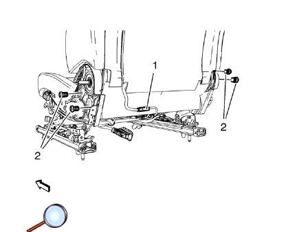
- Release and disconnect wiring harness plug (1), if equipped.
- Remove front seat backrest screw (2) (Qty: 4).
- Remove backrest.
- Detach cushion cover (1) from seat frame (3) all the way round.
- Remove cushion cover (1) with pad (2) from frame (3).
- Remove cushion cover (1) from pad (2).
Installation Procedure

- Install cushion cover (1) to pad (2).
- Install cushion cover (1) with pad (2) to frame (3).
- Attach cushion cover (1) from seat frame (3) all the way round.
- Install backrest.
Caution: Refer to Fastener Caution in the Preface section.
- Tighten screw (2) (Qty: 4).
Tighten 35 N·m (26 lb ft)
- Connect and latch wiring harness plug (1), if equipped.
- Attach cushion cover to backrest below.
- Install seat cushion outer trim panel. Refer to Front Seat Cushion Outer Trim Panel Replacement.
- Install seat cushion inner trim panel. Refer to Front Seat Cushion Inner Trim Panel Replacement.
- Install front seat recliner handle. Refer to Driver or Passenger Seat Recliner Handle Replacement.
- Install front seat adjuster handle, if equipped.
- Install driver or passenger seat. Refer to Driver or Passenger Seat Replacement.
 Front Seat Track Synchronization
The fore/aft manual adjuster is composed of an inboard track assembly (5),
and outboard track (4) assembly, and an adjuster handle (1).
Each track assembly is made of an upper track (2) and a ...
 Driver or Passenger Seat Back Cushion Cover and Pad Replacement
Removal Procedure
Warning: Refer to SIR Warning in the Preface section.
Warning: Replace the passenger presence system as a complete assembly to prevent
possible injury to the occupant. The blad ...
Other materials:
Headlining Trim Panel Replacement (Without Sunroof)
Warning: Do not attempt to repair or alter the head impact
energy-absorbing material glued to the headliner or to the garnish
trims. If the material is damaged, replace the headliner and/or the garnish
trim. Failure to do so could result in personal injury.
Caution: If a vehicle is equip ...
Tire Pressure Monitor
This vehicle may have a Tire Pressure Monitor System (TPMS).
The low tire pressure warning light alerts to a significant loss in pressure
of one of the vehicle's tires. If the warning light comes on, stop as soon as possible
and inflate the tires to the recommended pressure shown on the T ...
Exterior Windnoise
Warning: Refer to Assistant Driving Warning in the Preface section.
Exterior windnoise is louder when the vehicle is driven with one or more
windows down. Exterior windnoise occurs when air passes over
the body panels, the seams, or the openings. Use the following items during the
test drive i ...
