Chevrolet Cruze Repair Manual: Installation Procedure
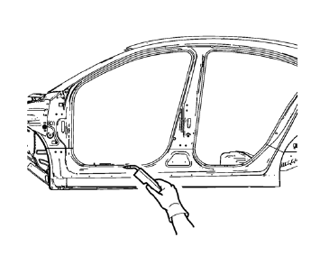
- Cut the rocker outer panel in corresponding locations to fit the remaining original panel. The sectioning joint should be trimmed to allow a gap of one-and-one-half-times the metal thickness at the sectioning joint.
- Create a 50 mm (2 in) backing plate from the unused portion of the service part.
- Drill 8 mm (5/16 in) along the sectioning cut on the remaining original part. Locate these holes 13 mm (1/2 in) from the edge of part and spaced 40 mm (1½ in) apart.
- Prepare all mating surfaces as necessary.
- Fit the backing plates halfway into the sectioning joints, clamp in place and plug weld to the vehicle.
- Align the rocker outer panel.
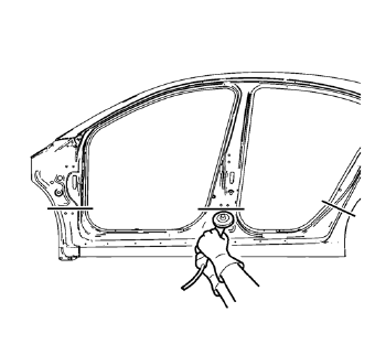
- Drill 8 mm (5/16 in) for plug welding along the edges of the rocker outer panel as noted from the original panel.
- Clean and prepare the attaching surfaces for welding.
- Position the rocker outer panel on the vehicle.
- Verify the fit of the rocker outer panel.
- Clamp the rocker outer panel into position.
- Plug weld accordingly.
- To create a solid weld with minimum heat distortion, make 25 mm (1 in) stitch welds along the seam with 25 mm (1 in) gaps between them. Then go back and complete the stitch weld.
- Apply the sealers and anti-corrosion materials to the repair area, as necessary. Refer to Anti-Corrosion Treatment and Repair.
- Paint the repaired area. Refer to Basecoat/Clearcoat Paint Systems.
- Install all related panels and components.
- Connect the negative battery cable. Refer to Battery Negative Cable Disconnection and Connection.
- Enable the SIR system. Refer to SIR Disabling and Enabling.
 Removal Procedure
Warning: Refer to Approved Equipment for Collision Repair Warning in the
Preface section.
Warning: Refer to Collision Sectioning Warning in the Preface section.
Warning: Refer to Glass and She ...
 Rocker Outer Panel Sectioning (MIG-Brazing)
Note: According to different corrosion warranties, only the
regional mandatory joining methods are allowed. ...
Other materials:
Tire Sealant and Compressor Kit
WARNING
Idling a vehicle in an enclosed area with poor ventilation is dangerous. Engine
exhaust may enter the vehicle. Engine exhaust contains carbon monoxide (CO) which
cannot be seen or smelled.
It can cause unconsciousness and even death. Never run the engine in an enclosed
area that has ...
Installation Procedure
Prepare all mating surfaces as necessary
Align the body lock pillar outer panel reinforcement.
Drill 8 mm (5/16 in) for plug welding along the edges of the body lock
pillar outer panel reinforcement as noted from the original
panel.
Clean and prepare the attaching surfac ...
Installation Procedure
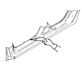
Cut the front compartment upper side rail in corresponding locations to
fit the remaining original panel. The sectioning joint should
be trimmed to allow a gap of one-and-one-half-times the metal thickness at
the sectioning joint.
Create a 50 mm (2 in) backing plate from the unused ...
