Chevrolet Cruze Repair Manual: Installation Procedure
- Install the following components on the drivetrain and front suspension frame if removed:
- The radiator support brackets.
- The stabilizer shaft--Refer to Stabilizer Shaft Replacement.
- The lower control arms--Refer to Lower Control Arm Replacement.
- The steering gear--Refer to Steering Gear Replacement
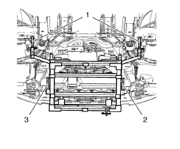
Note: Positioning pins (1) of CH 49289 adapter MUST be extended in order to guide into underbody holes.
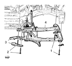
- Raise the frame (4) carefully, 2. using CH 49289 adapter .
- Install the frame reinforcements (3).
Caution: Refer to Fastener Caution in the Preface section.
Note: Do NOT reuse old bolts.
- Install the NEW frame rear bolts (2) and tighten to 160 N·m (118 lb ft).
Note: Do NOT reuse old bolts.
- Install the NEW frame front bolts (1) and tighten to 160 N·m (118 lb ft).
- Remove the support of the power steering gear
- Install the front bumper energy absorber bracket bolt. Refer to Front Bumper Energy Absorber Bracket Replacement.
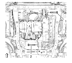
- Install the front transmission mount bolt (1) and tighten to 100 N·m (74 lb ft).
- Install the rear transmission mount bracket bolt (2) and tighten to 100 N·m (74 lb ft).
- Install the outer tie rods and tie rod nuts to the steering knuckles. Refer to Steering Linkage Outer Tie Rod Replacement.
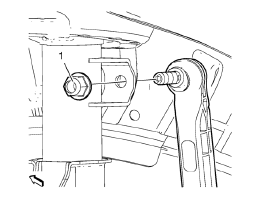
- Install the steering linkage tie rod. Tighten the steering linkage tie rod nut to 35 N·m (26 lb ft).
- Install the lower ball joints to the steering knuckles. Refer to Lower Control Arm Replacement.
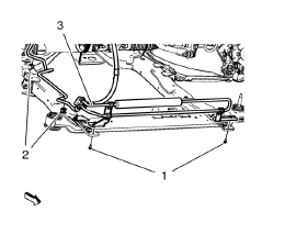
- Install the power steering fluid cooling pipe (3) to the frame, install
the power steering fluid cooling pipe bolt (1) and clip in (2).
Tighten the power steering fluid cooling pipe bolt to 9 N·m (80 lb in).
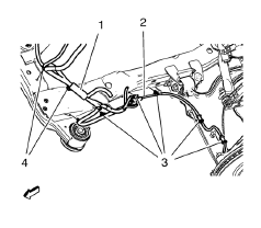
- Install the wheel speed sensor wiring harness (2) to the frame on both
sides.
Install the wiring harness retainers (3) to the frame and the lower control arm.
- Install the radiator wiring harness (1) to the frame.
Install the wiring harness retainers (4) to the frame.
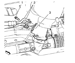
- Install the inlet and outlet hose (2) to the steering gear (3).
- Install power steering gear inlet and outlet hose bolts (1) and tighten to 11 N·m (97 lb in).
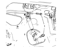
- Install the lower steering intermediate shaft (1) bolt and tighten to 34 N·m (25 lb ft).
- Remove the support of the radiator and condenser.
- Lower the vehicle on a hoist. Refer to Lifting and Jacking the Vehicle.
- Install the tire and wheel assemblies. Refer to Tire and Wheel Removal and Installation.
- Install the exhaust flexible pipe. Refer to Exhaust Flexible Pipe Replacement.
- Install the front bumper fascia opening lower cover. Refer to Front Bumper Fascia Opening Lower Cover Replacement.
- Install the engine splash shields. Refer to Front Compartment Splash Shield Replacement.
- Install the front compartment insulator, if equipped. Refer to Front Compartment Insulator Replacement.
- If replacing the frame, check the wheel alignment. Refer to Wheel Alignment Measurement.
 Removal Procedure
Support the radiator and condenser from above using the
condenser tabs on each side.
Remove the lower steering intermediate shaft bolt (1).
Raise the vehicle on a hoist. Refer to Li ...
 Drivetrain and Front Suspension Frame Insulator Replacement
Special Tools
CH 49460-1 Adapter
CH 49460-2 Adapter
CH 6616 Hydraulic Hand Pump
CH 6615-10 Hydraulic Cylinder
CH-48377-1 Chisel
For equivalent regional tools. Refer to Special Tools. ...
Other materials:
Front Bumper Fascia Guide Replacement
Preliminary Procedure
Remove the front bumper fascia. Refer to Front Bumper Fascia Replacement.
Front Bumper Fascia Guide Rivet (Qty: 2)
Headlamp Bolt
Caution: Refer to Fastener Caution in the Preface section.
Tighten
2.5 N·m (23 lb in)
Front Bumper Fascia Guide
Front Bumper ...
Removal Procedure
Warning: Refer to Approved Equipment for Collision Repair Warning in the
Preface section.
Warning: Refer to Glass and Sheet Metal Handling Warning in the Preface section.
Disable the SIR System. Refer to SIR Disabling and Enabling.
Disconnect the negative battery cable. Refer to Bat ...
Antilock Brake System (ABS)
This vehicle has the Antilock Brake System (ABS), an advanced electronic braking
system that helps prevent a braking skid.
When the vehicle begins to drive away, ABS checks itself.
A momentary motor or clicking noise might be heard while this test is going on,
and it might even be noticed that ...
