Chevrolet Cruze Repair Manual: Mirrors
Specifications
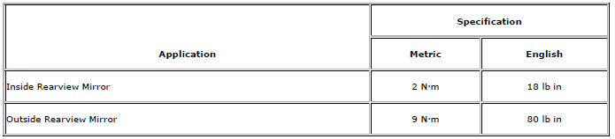
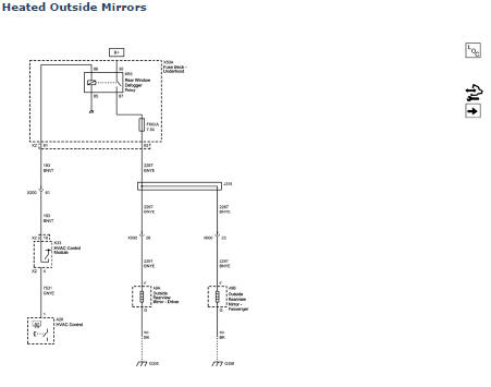
Inside Rearview Mirror Schematics
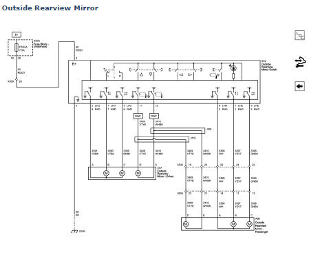
Outside Rearview Mirror Schematics
Outside Rearview Mirror Replacement
Preliminary Procedure
- Remove the front side door trim. Refer to Front Side Door Trim Replacement.
- Remove the front side door upper trim cover. Refer to Front Side Door Upper Trim Cover Replacement.
- Outside Rearview Mirror Mount Plate Bolt (Qty: 3)
Caution: Refer to Fastener Caution in the Preface section.
Tighten 9 N·m (80 lb in)
- Outside Rearview Mirror
Tip
Disconnect electrical connector.
Outside Remote Control Rearview Mirror Switch Replacement
Preliminary Procedure
- Remove front side door trim. Refer to Front Side Door Trim Replacement.
- Remove front side door window switch bezel. Refer to Front Side Door Window Switch Bezel Replacement.
- Side Window Switch Bezel
- Power Mirror Switch
Procedure
- Using a plastic pry tool, gently pry on the sides to release the switch.
- Disconnect the electrical connector.
Outside Rearview Mirror Motor Replacement
Preliminary Procedure
Remove the outside rearview mirror glass. Refer to Outside Rearview Mirror Glass Replacement.
- Outside Rearview Mirror Motor Bolt (Qty: 3)
Caution: Refer to Fastener Caution in the Preface section.
Tighten 3 N·m (27 lb in).
- Outside Rearview Mirror Motor
Tip
Disconnect the electrical connector.
Outside Rearview Mirror Glass Replacement

Warning: Refer to Glass and Sheet Metal Handling Warning in the Preface section.
Outside Rearview Mirror Glass
Procedure
- Release the mirror glass backing from the mirror housing by pulling outward.
Tip
Disconnect the power wire harness electrical connector.
Outside Rearview Mirror Housing Replacement
Preliminary Procedure
Remove outside rearview mirror glass. Refer to Outside Rearview Mirror Glass Replacement.
- Outside Rearview Mirror Housing Screw (Qty: 4)
Caution: Refer to Fastener Caution in the Preface section.
Tighten 2.5 N·m (22 lb in)
- Lower Outside Rearview Mirror Housing Screw
Tighten 2.5 N·m (22 lb in)
- Outside Rearview Mirror Housing
Tip
Disconnect electrical connector.
Inside Rearview Mirror Replacement
Preliminary Procedure
- Remove the outside moisture cover. Refer to Windshield Outside Moisture Sensor Cover Replacement
- Adjust the mirror to the full upward position.
Inside Rearview Mirror Bolt
Caution: Refer to Fastener Caution in the Preface section.
Tighten 8 N·m (80 lb in)
Inside Rearview Mirror
Tip
Slide the mirror in an upward motion in order to remove.
 Interior Lamps Dimming
This group includes lamps which may dim. This group may use a combination of
vacuum fluorescent illumination, LEDs and incandescent
lamps
HVAC control module, head assembly
Rear HVAC control ...
 Vehicle Access
Specifications
Door Lock/Indicator Schematics
Door Control Module Schematics
Release Systems Schematics
Fuel Tank Filler Door Lock Actuator Replacement
...
Other materials:
Removal Procedure
Warning: Refer to Approved Equipment for Collision Repair Warning in the
Preface section.
Warning: Refer to Collision Sectioning Warning in the Preface section.
Warning: Refer to Glass and Sheet Metal Handling Warning in the Preface section.
Disable the SIR System. Refer to SIR Disabling ...
Immobilizer Operation
This vehicle has a passive theft-deterrent system.
The system does not have to be manually armed or disarmed.
The vehicle is automatically immobilized when the key is removed from the ignition.
The system is automatically disarmed when the vehicle is started with the correct
key. The key uses a ...
Tyre Dismounting and Mounting
Caution: Use a tire changing machine in order to dismount tires. Do
not use hand tools or tire irons alone in order to remove the tire from
the wheel. Damage to the tire beads or the wheel rim could result.
Caution: Do not scratch or damage the clear coating on aluminum wheels with the
tire ...
