Chevrolet Cruze Repair Manual: Power Door Locks Description and Operation
Door Lock System Components
The power door lock system consists of the following components:
- Door lock switch - located in the center of the instrument panel
- Body control module (BCM)
- Driver door latch
- Passenger door latch
- Left rear door latch
- Right rear door latch
Door Lock System Controls
The power door lock system can be controlled by any of the following:
- Power door lock switch activation
- Keyless entry lock or unlock command
- A door lock cylinder switch Unlock actuation
- Delayed locking command
- Automatic door lock command
Door Lock and Unlock Operation
When a door lock switch is activated in the lock or unlock position the BCM will receive a ground signal on either the door lock switch lock or unlock signal circuits.
The BCM, upon receipt of a lock switch lock or unlock signal, will supply battery voltage to the door lock actuator lock or unlock control circuits. Since the opposite side of the lock actuator is connected to ground through the other lock actuator control circuit, the doors, fuel filler door and liftgate will then lock or unlock as commanded.
The following three circuits are used to operate the lock:
- Driver door unlock
- Passenger door unlock
- All door lock
The driver door lock actuator is isolated so it can be unlocked by itself using the keyless entry transmitter.
Automatic Door Lock Operation
This feature can be personalized to driver preference.
The BCM will automatically lock the vehicle doors if the following conditions exist:
- All vehicles doors are closed.
- The ignition is in the ON position
- The vehicle is shifted out of Park.
The BCM will then unlock the doors when vehicle is shifted back into Park.
Delayed Locking Operation
With any door open and a door lock switch is activated in the lock position, the BCM will give three audible chimes. When the door is closed, the BCM will cycle the internal door lock relay to lock the doors after approximately five seconds. This feature can be overridden by activating the door lock switch a second time and the doors will lock even with a door open.
Lockout Prevention Operation
The BCM will lock all doors and unlock the driver door with a door lock switch lock activation if a vehicle door is open and the ignition key is fully inserted in the ignition. The lockout prevention feature can be overridden if a lock command is received from the keyless entry system.
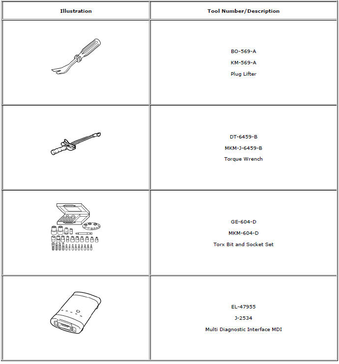
Special Tools and Equipment
 Power Door Latch Description and Operation
Power Door Latch System Components
The power door latch system consists of the following components:
Remote control door lock receiver
Body control module (BCM)
Driver door latch
Passenger ...
 Wipers and Washers
Specifications
Wiper/Washer Schematics
Windshield Wiper and Washer Switch Replacement
Preliminary Procedure
Remove the steering column trim covers. Refer to Steering Column Low ...
Other materials:
Filling the Tank
WARNING
Fuel vapors and fuel fires burn violently and can cause injury or death.
• To help avoid injuries to you and others, read and follow all the instructions
on the fuel pump island.
• Turn off the engine when refueling.
• Keep sparks, flames, and smoking materials away from fuel.
• Do no ...
Tire Changing
Removing the Spare Tire and Tools
To access the spare tire and tools:
1. Retainer Nut.
2. Tool Bag Tether.
3. Tool Bag.
4. Spare Tire.
1. Open the trunk.
2. Lift the load floor.
3. Turn the retainer nut (1) counterclockwise to remove it.
Then remove the tool bag tether (2) from th ...
Low-Profile Tires
If the vehicle has P225/45R18 size tires, they are classified as low‐profile
tires. These tires are designed for very responsive driving on wet or dry pavement,
however, may produce more road noise and tend to wear faster.
Notice: Low-profile tires are more susceptible to damage from road ...
