
Chevrolet Cruze Repair Manual: Removal Procedure
Warning: Refer to Approved Equipment for Collision Repair Warning in the Preface section.
Warning: Refer to Collision Sectioning Warning in the Preface section.
Warning: Refer to Glass and Sheet Metal Handling Warning in the Preface section.
- Disable the SIR System. Refer to SIR Disabling and Enabling.
- Disconnect the negative battery cable. Refer to Battery Negative Cable Disconnection and Connection.
- Remove all related panels and components.
- Visually inspect the damage. Repair as much of the damage as possible.
- Remove the sealers and anti-corrosion materials from the repair area, as necessary. Refer to Anti-Corrosion Treatment and Repair.
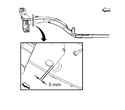
- Create cut lines on the front compartment front rail.
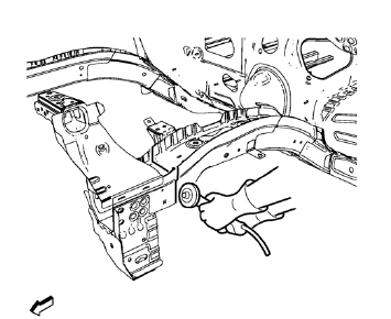
Note: Do not damage internal reinforcement of front compartment side rail.
- Cut the panel where sectioning is to be performed.
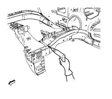
Note: Left side only.
- Locate and mark all the necessary factory welds of the front compartment front rail.
- Drill all factory welds. Note the number and location of welds for installation of the service assembly.
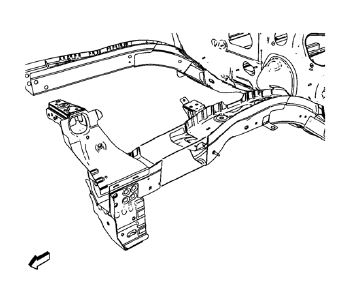
- Remove the damaged front compartment front rail.
 Front Compartment Side Rail Sectioning (Short, MIG-Brazing)
Note: According to different corrosion warranties, only the
regional mandatory joining methods are allowed. ...
 Installation Procedure
Cut the front compartment front rail in corresponding locations to fit
the remaining original panel. The sectioning joint should be
trimmed to allow a gap of one-and-one-half-times the met ...
Other materials:
Low-Profile Tires
If the vehicle has P225/45R18 size tires, they are classified as low‐profile
tires. These tires are designed for very responsive driving on wet or dry pavement,
however, may produce more road noise and tend to wear faster.
Notice: Low-profile tires are more susceptible to damage from road ...
General Information
Your vehicle is an important investment. This section describes the required
maintenance for the vehicle. Follow this schedule to help protect against major
repair expenses resulting from neglect or inadequate maintenance. It may also help
to maintain the value of the vehicle if it is sold. It ...
Courtesy/Illuminated Entry Lamps
The following lamps may be manually turned ON by placing the interior lamp
switch in the ON position, or by opening a door while the
switch is in the AUTO position.
The dome lamp
The liftgate lamps
Courtesy lamps
The courtesy lamp supply voltage circuit of the body control module (BCM) ...
