
Chevrolet Cruze Repair Manual: Removal Procedure
Warning: Refer to Approved Equipment for Collision Repair Warning in the Preface section.
Warning: Refer to Collision Sectioning Warning in the Preface section.
Warning: Refer to Glass and Sheet Metal Handling Warning in the Preface section.
- Disable the SIR System. Refer to SIR Disabling and Enabling
- Disconnect the negative battery cable. Refer to Battery Negative Cable Disconnection and Connection.
- Remove all related panels and components.
- Visually inspect the damage. Repair as much of the damage as possible.
- Remove the sealers and anti-corrosion materials from the repair area, as necessary. Refer to Anti-Corrosion Treatment and Repair.
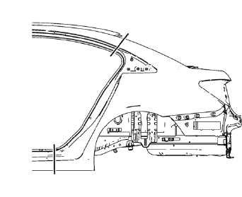
- Create cut lines on the quarter outer panel.
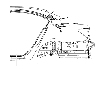
Note: Do not damage any inner panels or reinforcements.
- Cut the panel where sectioning is to be performed.
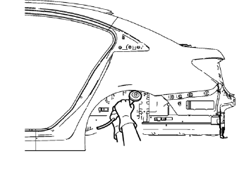
- Open the wheelhouse flanging.
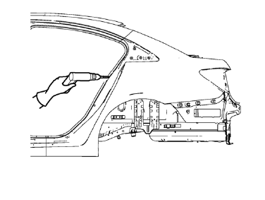
- Locate and mark all the necessary factory welds of the quarter outer panel.
- Drill all factory welds. Note the number and location of welds for installation of the service assembly.
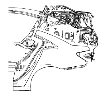
- Remove the damaged quarter outer panel.
 Quarter Outer Panel Sectioning (MAG-Welding)
Special Tools
BO-6396 Bonding Pliers
BO-6392 Flanging Tool Kit
For equivalent regional tools, refer to Special Tools
Note: According to different corrosion warranties, only the
regional ma ...
 Installation Procedure
Cut the quarter outer panel in corresponding locations to fit the
remaining original panel. The sectioning joint should be trimmed to
allow a gap of one-and-one-half-times the metal thickn ...
Other materials:
Turn and Lane-Change Signals
Move the lever all the way up or down to signal a turn.
An arrow on the instrument cluster will flash in the direction of the turn or
lane change.
Raise or lower the lever until the arrow starts to flash to signal a lane change.
The turn signal flashes three times.
The lever returns to its ...
Courtesy Transportation Program
To enhance your ownership experience, we and our participating dealers are proud
to offer Courtesy Transportation, a customer support program for vehicles with the
Bumper-to-Bumper (Base Warranty Coverage period in Canada), extended powertrain,
and/or hybrid-specific warranties in both the U.S ...
When Should an Airbag Inflate?
This vehicle has advanced technology frontal airbags. Frontal airbags are designed
to inflate in moderate to severe frontal or near frontal crashes to help reduce
the potential for severe injuries, mainly to the driver's or front outboard passenger's
head and chest.
However, they are ...
