
Chevrolet Cruze Repair Manual: Installation Procedure
- Prepare all mating surfaces as necessary
- Align the body lock pillar outer panel reinforcement.
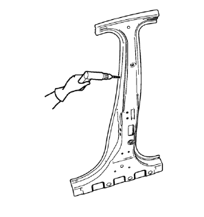
- Drill 8 mm (5/16 in) for plug welding along the edges of the body lock pillar outer panel reinforcement as noted from the original panel.
- Clean and prepare the attaching surfaces for welding.
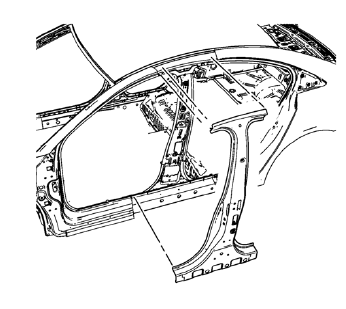
- Position the body lock pillar outer panel reinforcement on the vehicle.
- Verify the fit of the body lock pillar outer panel reinforcement
- Clamp the body lock pillar outer panel reinforcement into position.
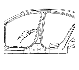
- Plug weld accordingly.
- To create a solid weld with minimum heat distortion, make 25 mm (1 in) stitch welds along the seam with 25 mm (1 in) gaps between them. Then go back and complete the stitch weld.
- Apply the sealers and anti-corrosion materials to the repair area, as necessary. Refer to Anti-Corrosion Treatment and Repair.
- Paint the repaired area. Refer to Basecoat/Clearcoat Paint Systems.
- Install all related panels and components.
- Connect the negative battery cable. Refer to Battery Negative Cable Disconnection and Connection.
- Enable the SIR system. Refer to SIR Disabling and Enabling.
 Removal Procedure
Warning: Refer to Approved Equipment for Collision Repair Warning in the
Preface section.
Warning: Refer to Glass and Sheet Metal Handling Warning in the Preface section.
Disable the SIR Syst ...
 Body Lock Pillar Outer Panel Reinforcement Replacement (MIG-Brazing)
Note: According to different corrosion warranties, only the
regional mandatory joining methods are allowed. ...
Other materials:
Installation Procedure
Drill 8 mm (5/16 in) for plug welding along the edges of the front
wheelhouse front panel as noted from the original panel.
Drill 8 mm (5/16 in) for plug welding where front wheelhouse front panel
and front wheelhouse overlap.
Clean and prepare the attaching surfaces f ...
Power Windows
WARNING
Children could be seriously injured or killed if caught in the path of a closing
window. Never leave keys in a vehicle with children. When there are children in
the rear seat, use the window lockout button to prevent operation of the windows.
Press the switch down to open the window. ...
Off-Road Recovery
The vehicle's right wheels can drop off the edge of a road onto the shoulder
while driving. Follow these tips:
1. Ease off the accelerator and then, if there is nothing in the way, steer the
vehicle so that it straddles the edge of the pavement.
2. Turn the steering wheel about one-eight ...
